updated 2014-05-18
2014-02-15
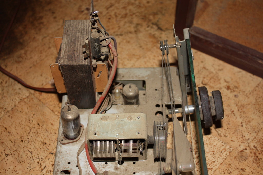
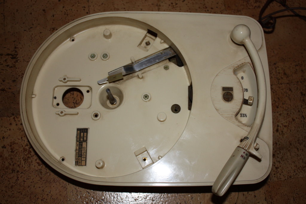
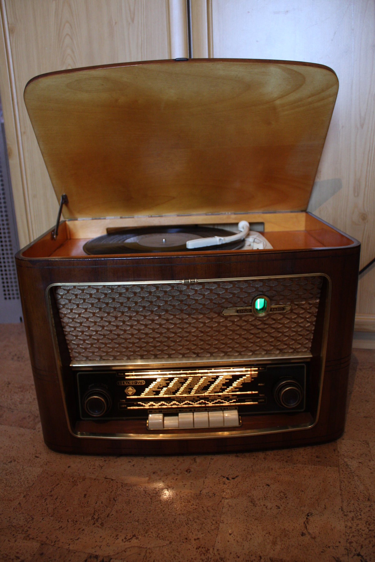
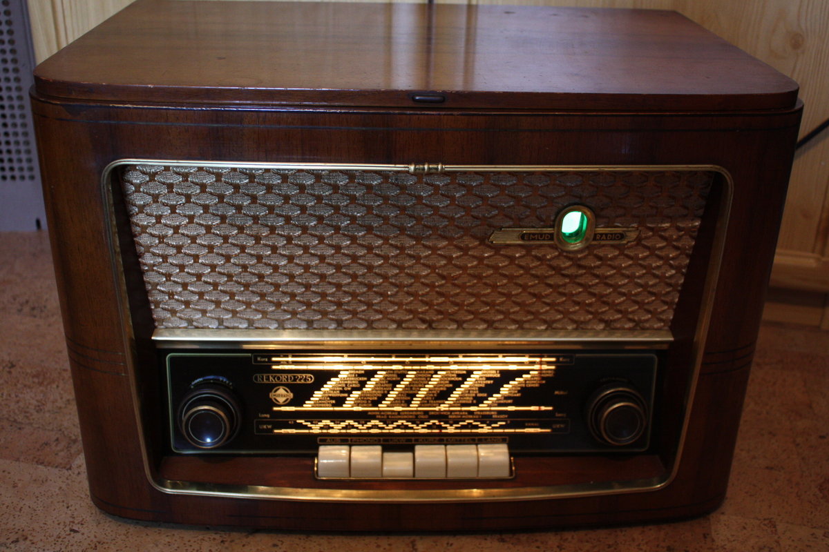
This weekend I started restoring an EMUD Phono Rekord 328 tube radio from 1956. The clue of this tube radio is its integrated record player - the "Rekord 225" tube radio was "augmented" with a "Philips AG2004" record player module. This is how it looked like when I got it:
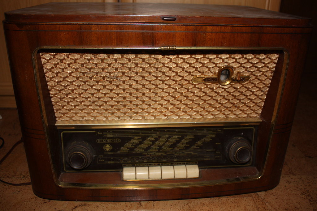
It has spent several years in the attic and collected some dust and corrosion. More details in the following photographs:
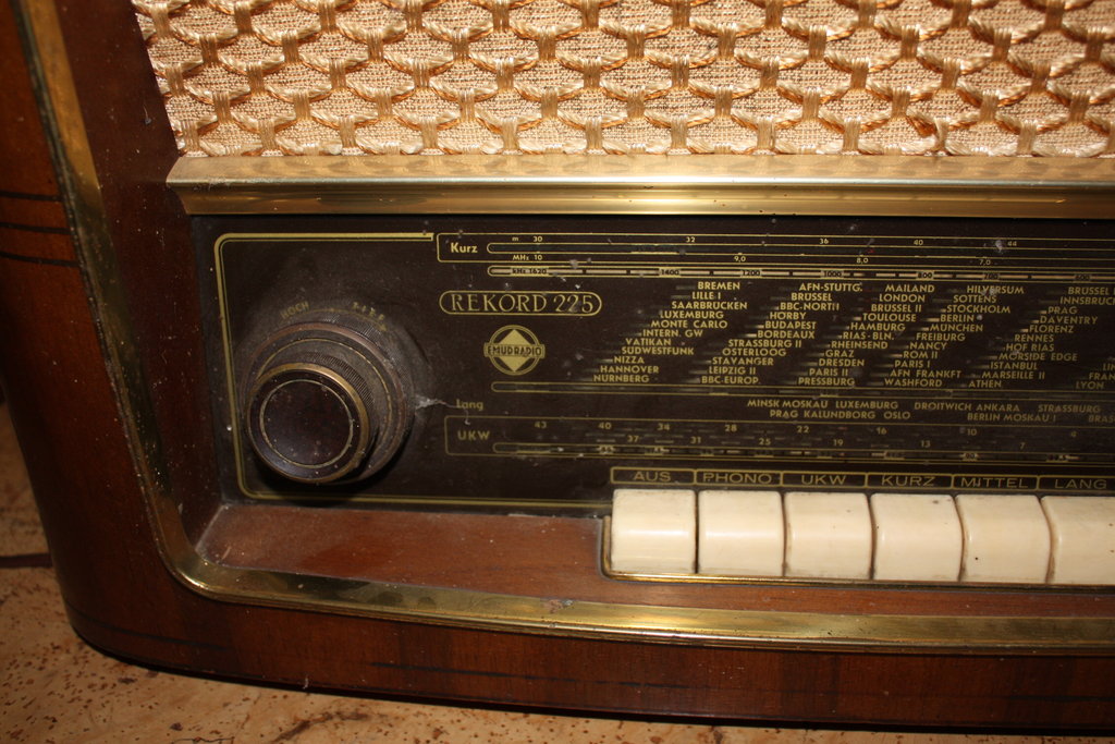
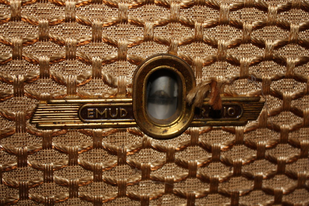
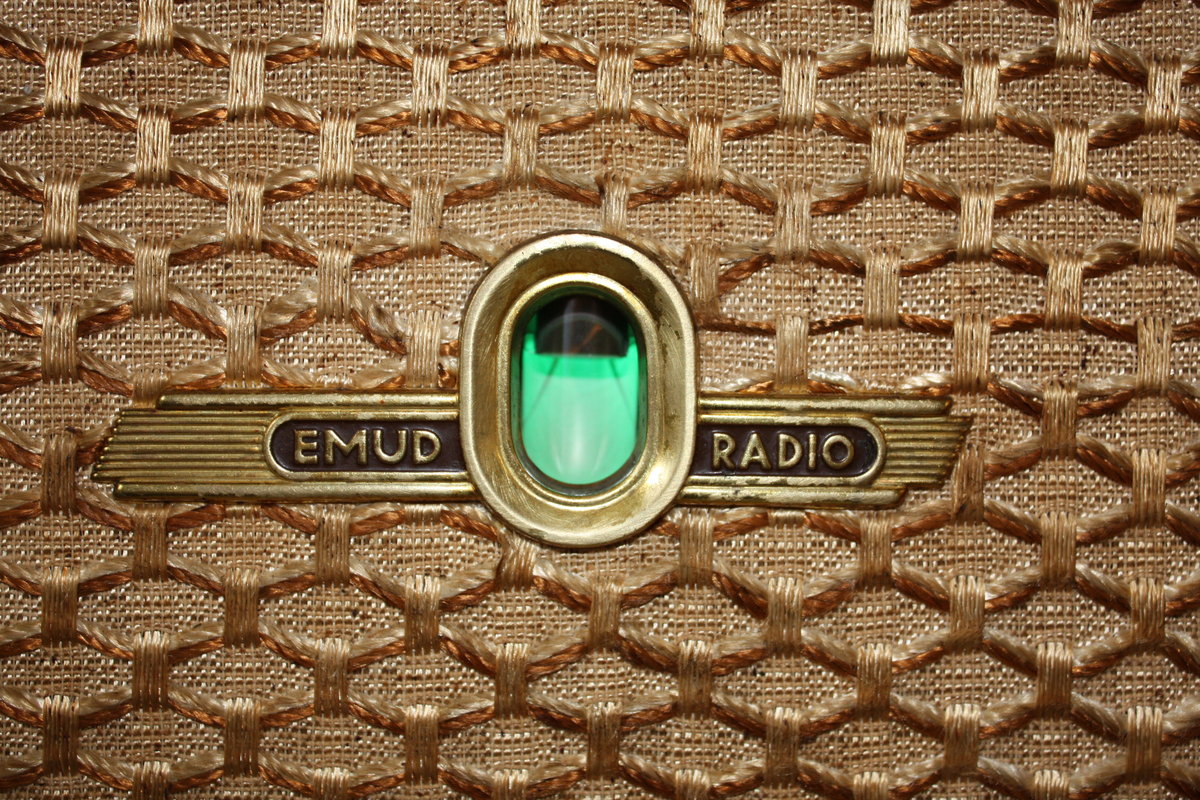
EMUD RADIO? Is this a strange no-name radio? No, it stands for Ernst Mästling Ulm Donau - the name and city + river of its manufacturer (using word creations like this as a name for your enterprise was typical for this time, another more famous one is e.g. IKEA) - and it was / is a high-quality product.
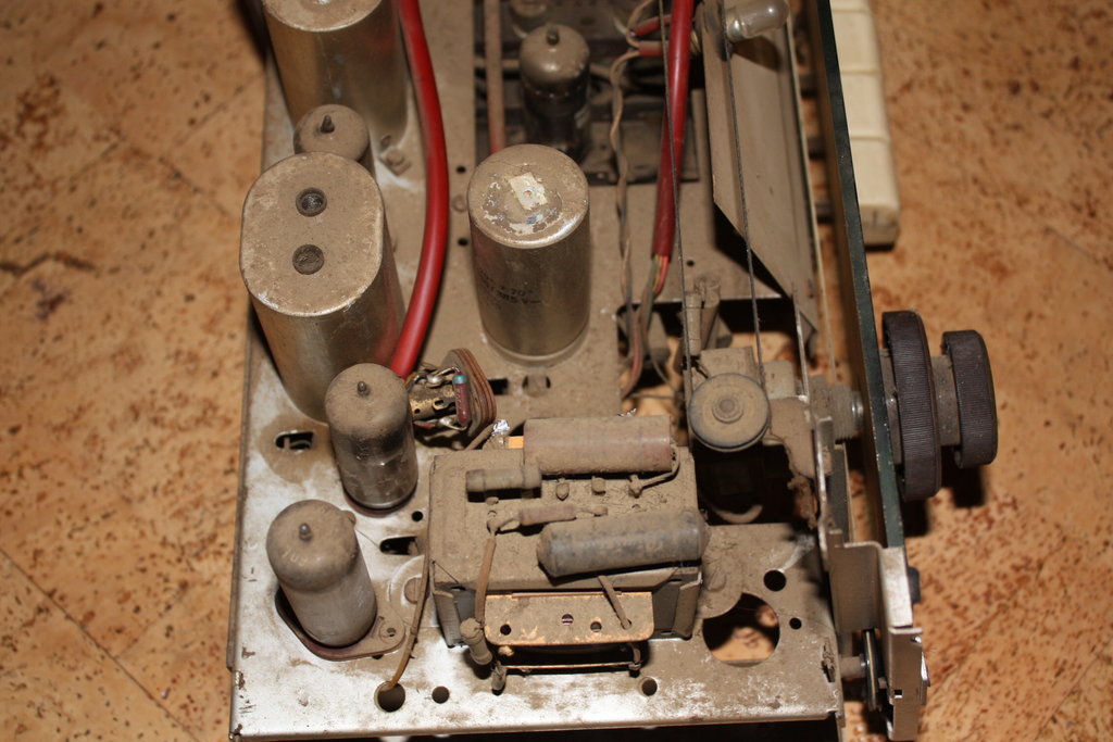
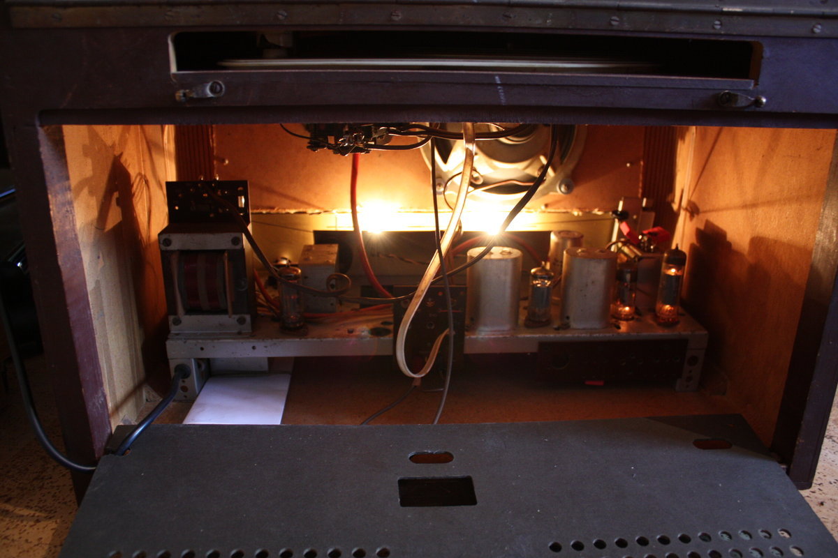
This is how it looks inside - quite dirty actually...


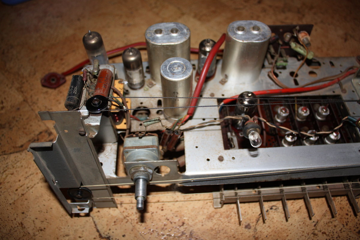
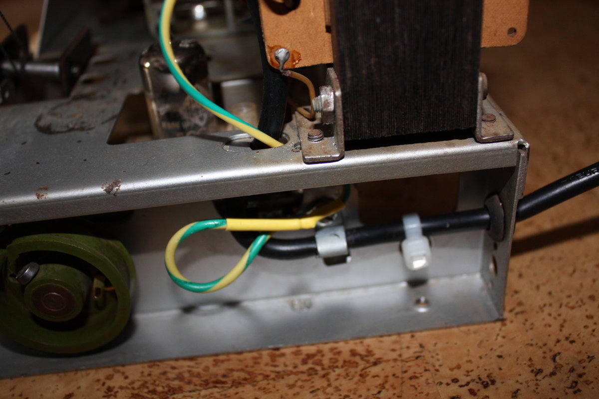
Getting the chassis out required some desoldering on the power transformer (upper left in next photo). The tube radio as well as the record player module are both powered by 230 (back in 1956 by 220) volts. Therefore some attention seems advisable to prevent electrocution...
The red cable leads to the socket of the EM80 magic eye indicator tube.
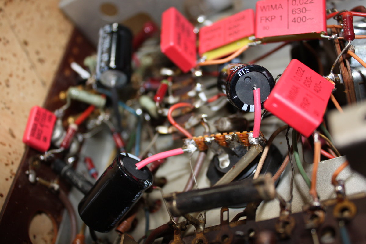
On the underside of the chassis is the typical discrete (chaotic =-) circuitry.
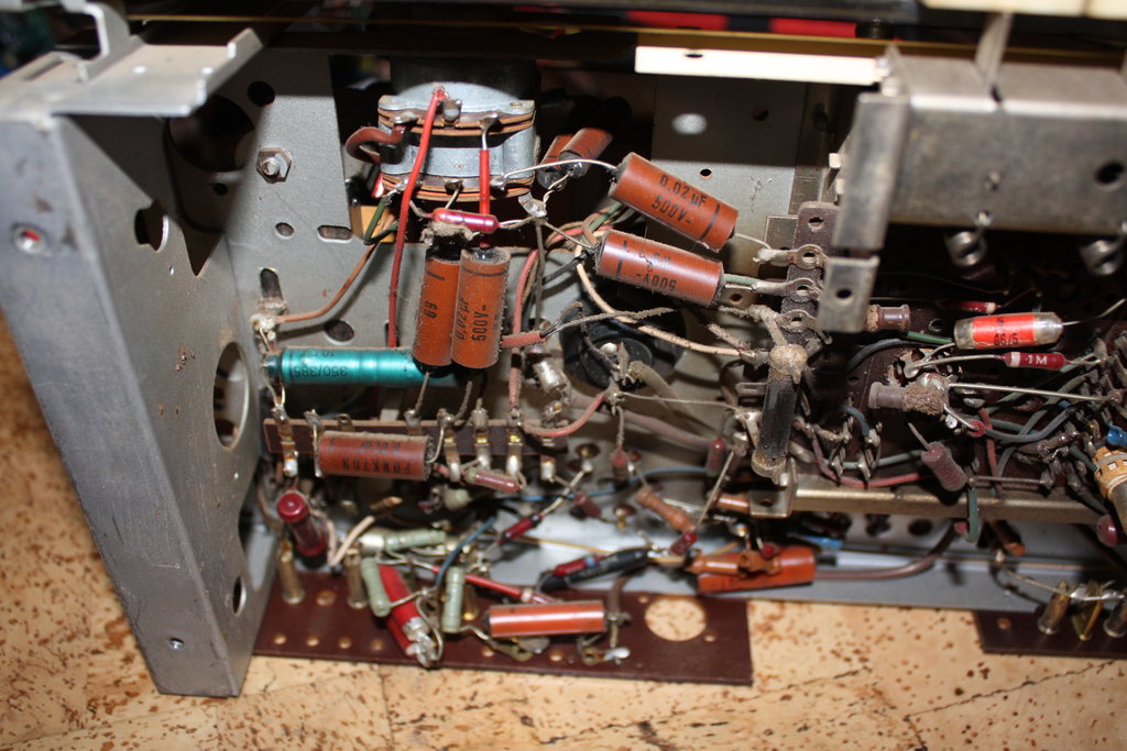
Luckily I found a circuit scheme on this great tube radio page. Restoring this radio will require removing most of the old and meanwhile bad capacitors i.e. all the brown "500V" guys and the blue one one the left (the "-" after the "500V" stands for DC in contrast to "~" which is AC - this is important for selecting the right replacement caps btw).
The lighted screen behind the dial glass has got quite dark and needs some new white colour to shine again.
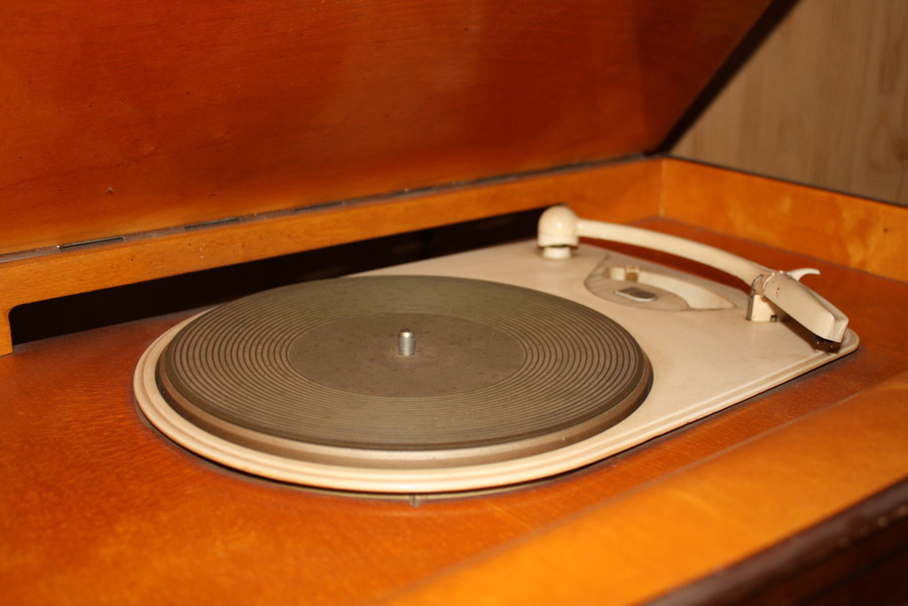
I started with cleaning the record player - most of the dirt (but sadly not all of it) could be removed by using an old toothbrush:
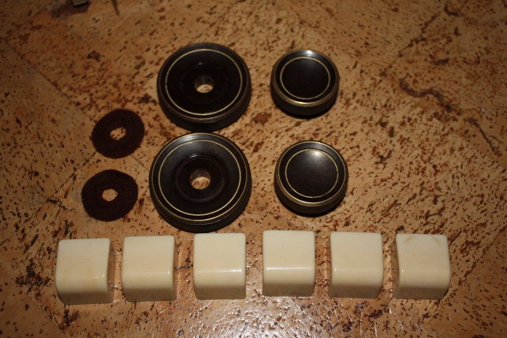
The knobs and buttons were easier to clean.
2014-03-04
Some status updates on my "EMUD-project":
Meanwhile I have cleaned the entire chassis from dust and grease. It required several hours and a lot of cleaning solvents and q-tips, but I´m quite content with the way it looks like now.
Another advantage of having removed the dust: Most capacitor values are much better readable now =-)
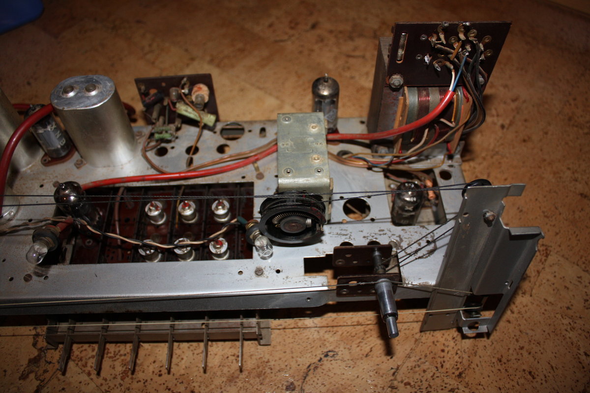
Additionaly, I lubricated all of the wheels of the dial cord tuning mechanism including the axes of the variable capacitors. The FM tuner dial cord is pretty worn and will probably need to be replaced.
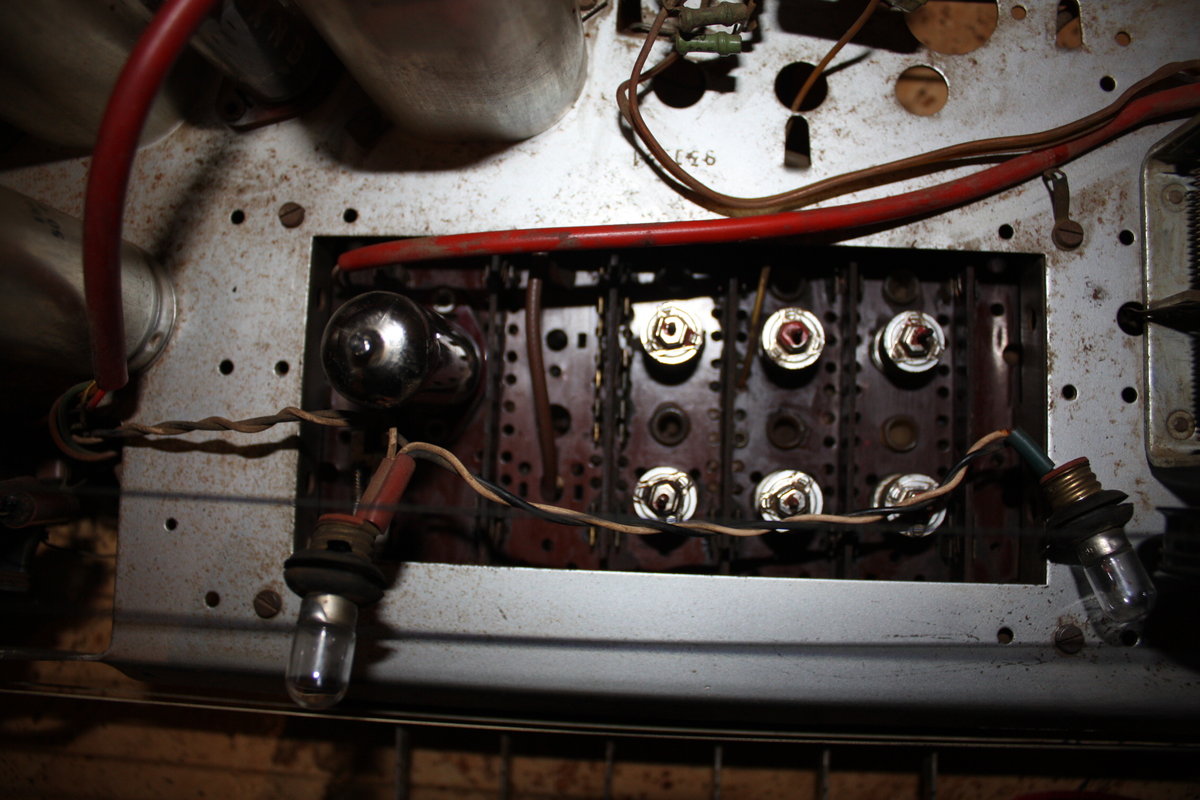
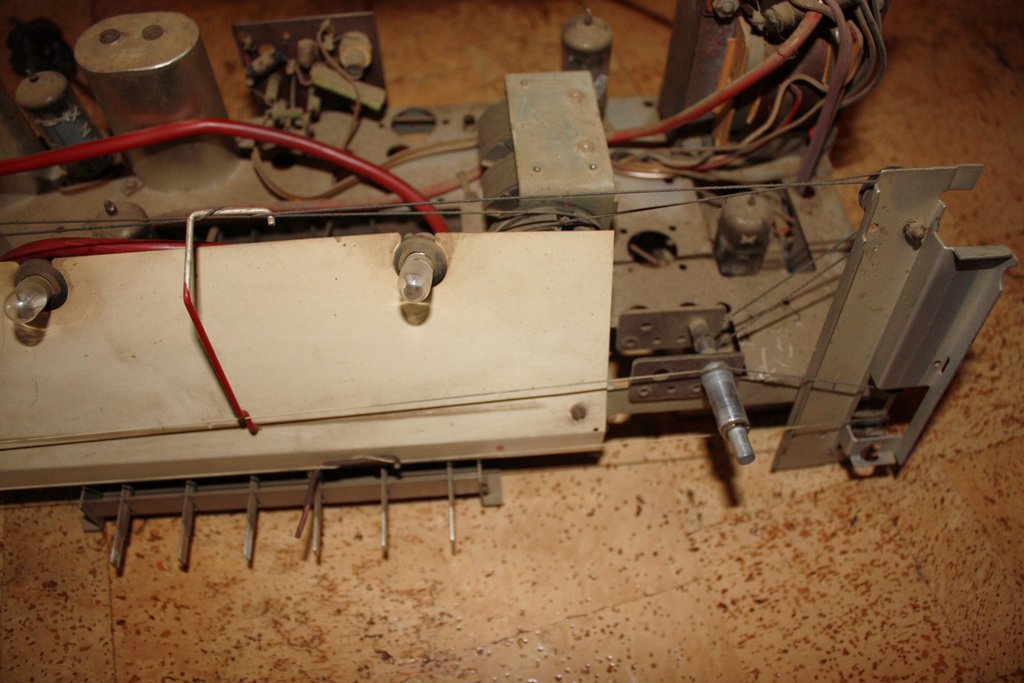
In the picture above you can see the six switches for changing the frequency range and amplifier mode of the radio. Each switch has a contact slider which opens / closes several contact pins when it is pressed. Therefore this was probably the most complicated part of cleaning the radio because the old pertinax circuit board material is quite fragile and there where really many of these small contact pins which had to be checked and cleaned (dental floss turned out to be quite useful here).
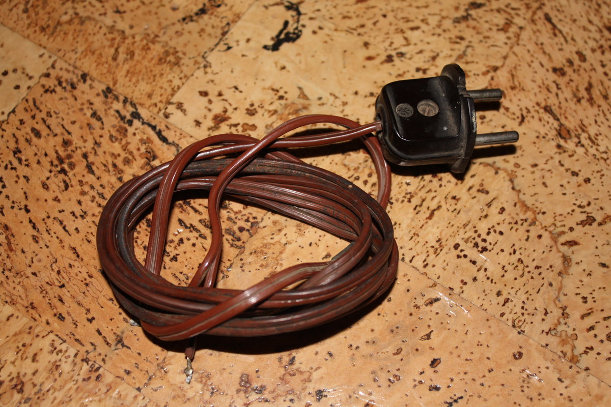
Something to amuse you at the end of today´s post: This is the original power cable of the radio - pretty unbelievable that this was seen as "sufficiently secure" in the late 1950s...maybe people back then were just more resistant to electrocution?
2014-03-10
The last weekend was very productive, but see for yourself...
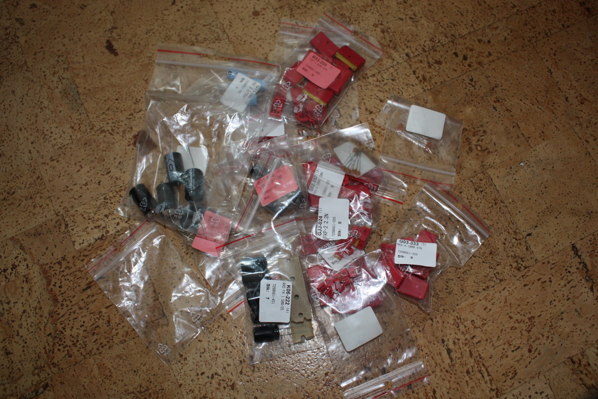
The first thing was replacing most of the ancient / faulty capacitors - here are the new ones which are supposed to last much longer.
Then...many hours of hard soldering work passed...until...

Above, the two new capacitors on the output transformer - below most of the other caps on the underside of the chassis.
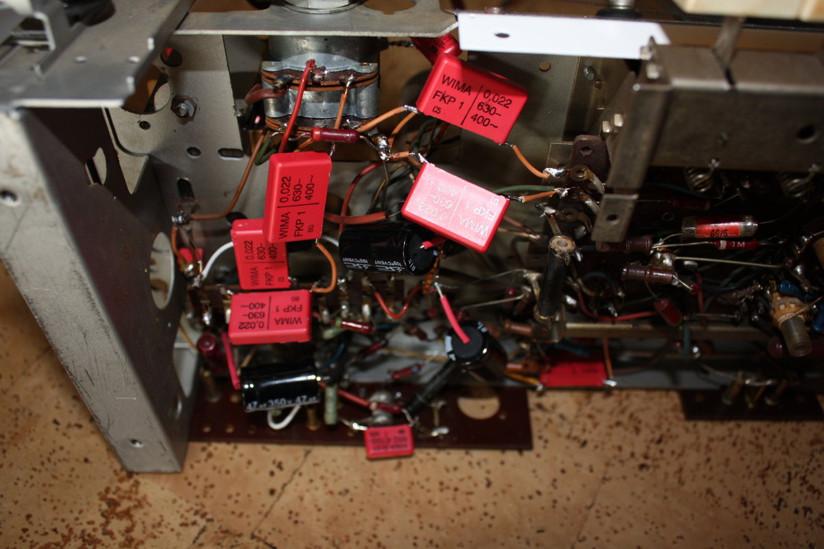
Don´t blame me for removing all old capacitors - I know that there are a lot of people out there who try to preserve tube radios in their original state (at least as far as possible). However, as the radio is supposed to be used regularly, I went the safe way (I just don´t want it to explode or sound bad...).
A way to preserve the nice looking old can capacitor (sic!) was to just bypass it with a piece of solder board and two new caps.
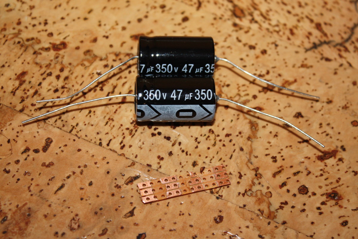
Look´s like that (and is much more secure than it was before):
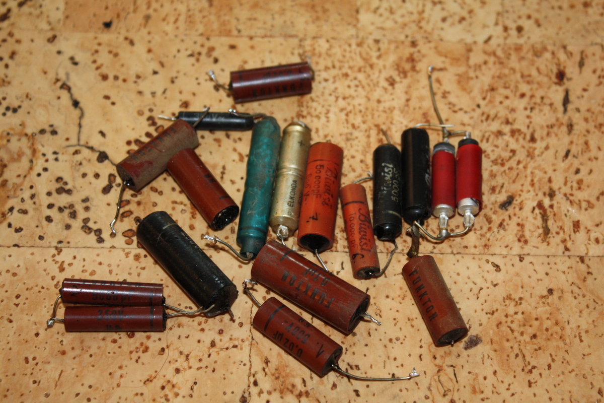
Here are the desoldered capacitors which will be kept together with the radio...
Now some other construction areas:
I installed a new power cable with PE line.
A problem I encountered on my way was the old FM tuner dial cord - it finally broke (it already had a number of minor damages) and I will replace it with a new one which I already ordered.

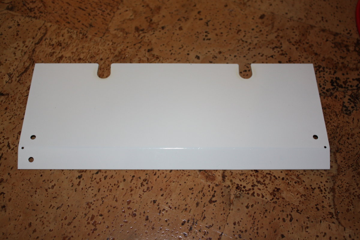
Here is the newly-coated dial backplane...soooo white (many thanks Timo =-).
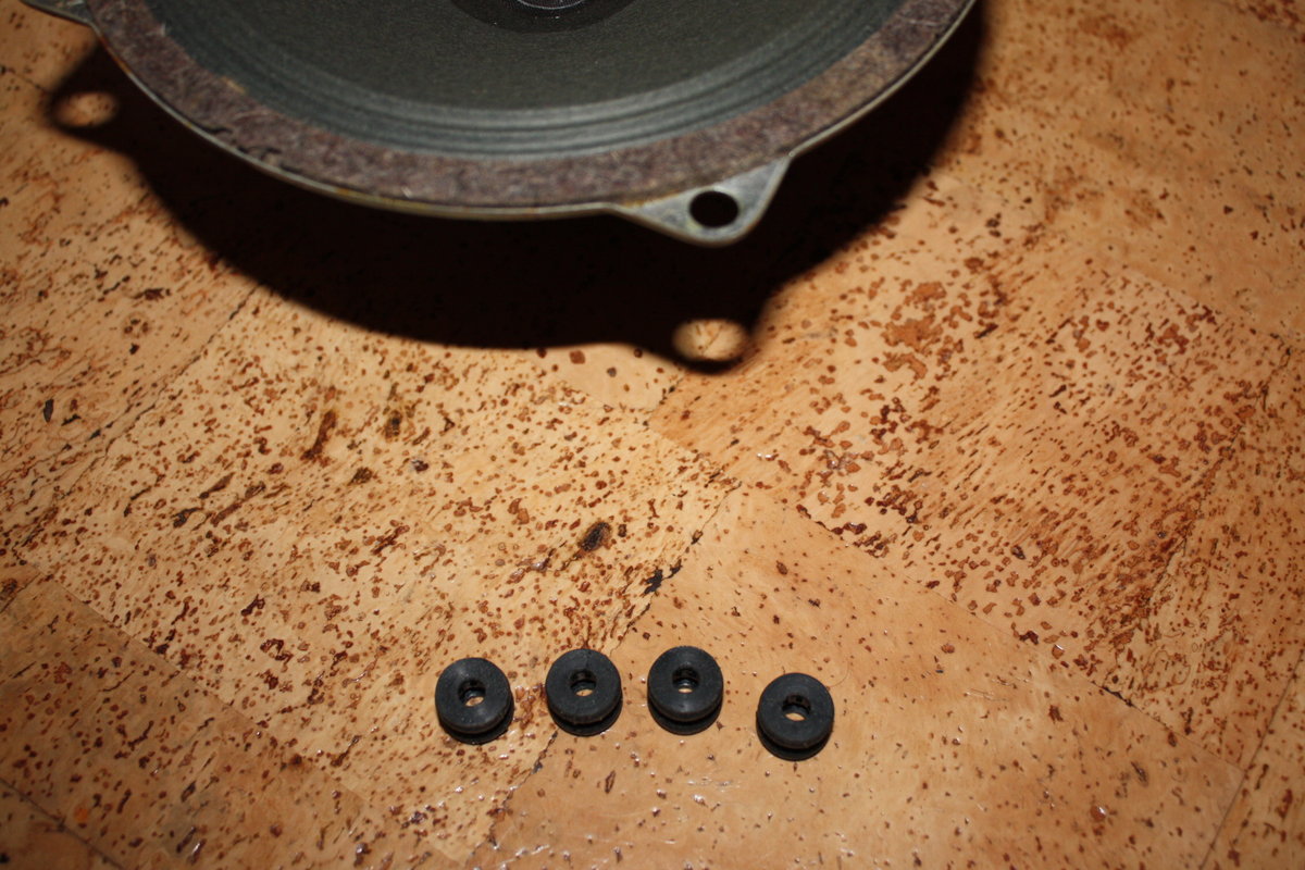
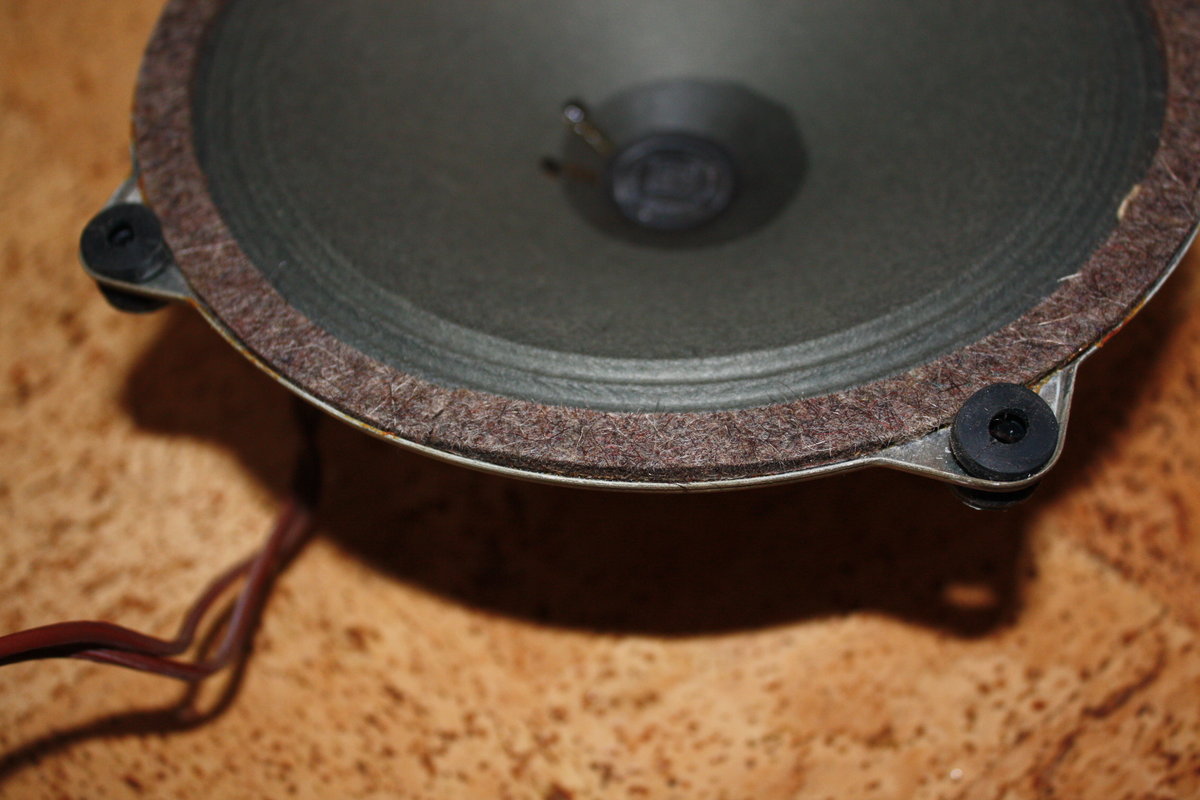
To improve the quality of the loudspeakers I replaced the old rubber decouplers...

...with new ones salvaged from a dead CD drive...
A simple way to remove fine fuzz on the loudspeaker fabric?
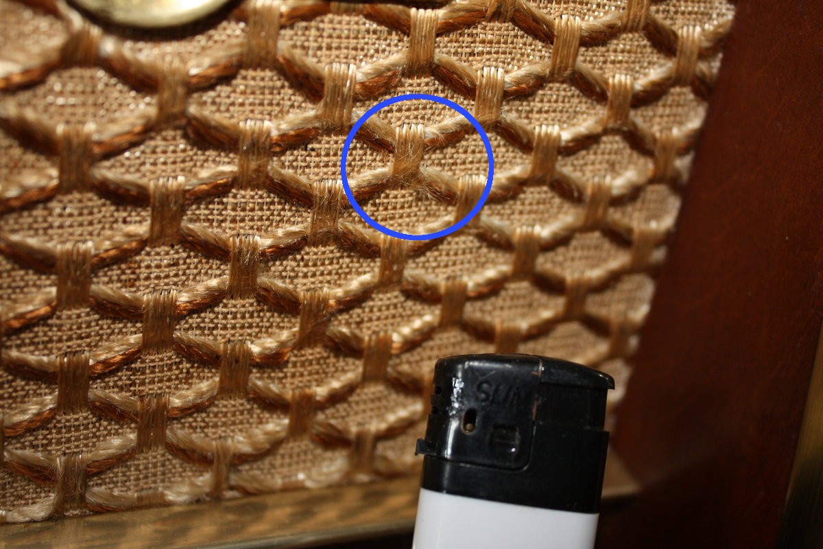
Burn it away...
2014-03-17 A DIY pickup for the EMUD radio record player
This post shows how I repaired the dead phono pickup.
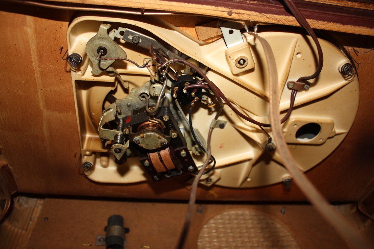
Above, the record player module as seen from below - the motor and drive was working instantly without many problems and needed just some basic cleaning and lubricating of the turntable axis. The pickup, however, showed no funtion at all.
As the cables were tested okay, I assumed the error in the phono head (pictured below).
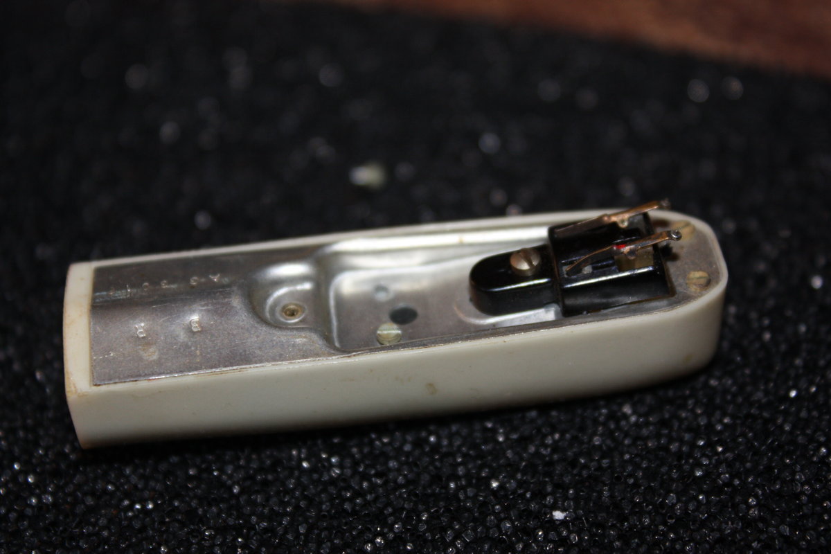
It is a push-on head and can be removed easily - the mounting arm was quite dirty but cleaning it did not solve the issue:
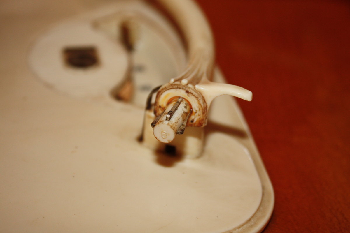
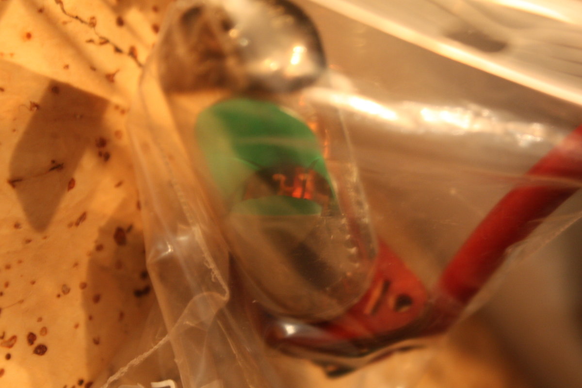
According to this site the phono pickup is a Philips AG3016 model which features a Potassium sodium tartrate crystal ("PSTC", a.k.a. Seignette´s salt) as a piezoelectric pickup. The pickup crystal (blue circle) is rubber mounted and connected to the two phonograph needles (orange circle, for shellac- and vinyl-based records).
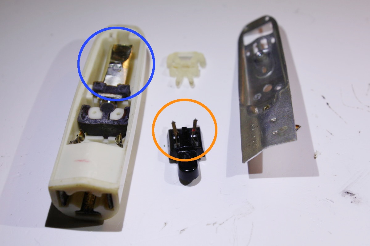
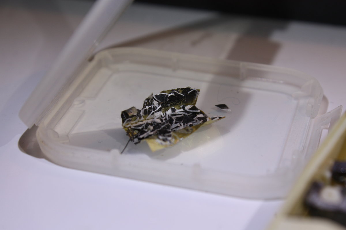
The problem with this crystal? It is not stable over time and after more than five decades it had decayed to white crystal shards.
To repair it I got some inspiration from here and from the homepage of John Hupse. I documented the steps in the following photograph.
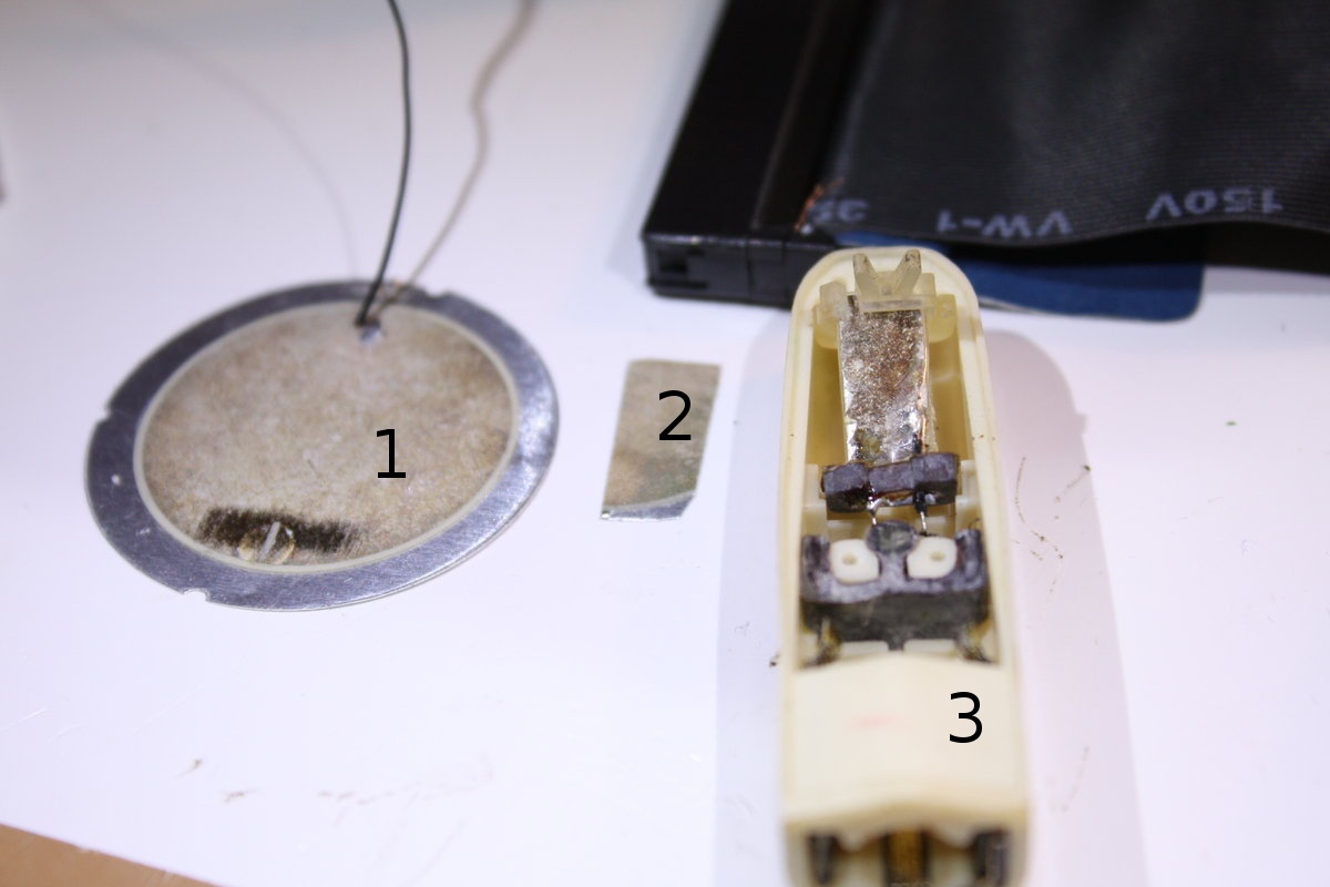
First I used very sharp and hard scissors to cut a piezo transducer (1) into the form of the old PSTC (2). Then I covered the piece with tape and put it into position in the pickup head where I soldered one of the two head contacts to the metal and the other to the crystal part of the piezo pickup (3).
As the pickup sounded quite tinny this way, I attached some tape strips to it, to reduce vibrations and dampen high pitched noises.

Testing this do-it-yourself pickup revealed good sound quality with mono sound records. Stereo records sound somewhat distorted but still acceptable, too. Overall I think it is a fast and affordable way to get the old Philips pickup back to business without destroying its structure.
2014-03-24 - Recalibration and test runs
In the past two weeks I did various "test runs" with the radio. After I had replaced the FM tuner dial cord, I put the dial glass back in place and tuned to many different radio stations.
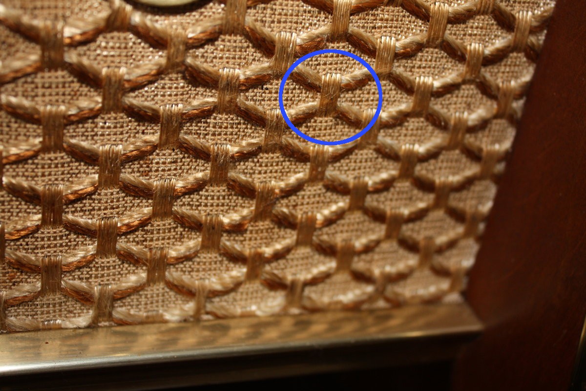
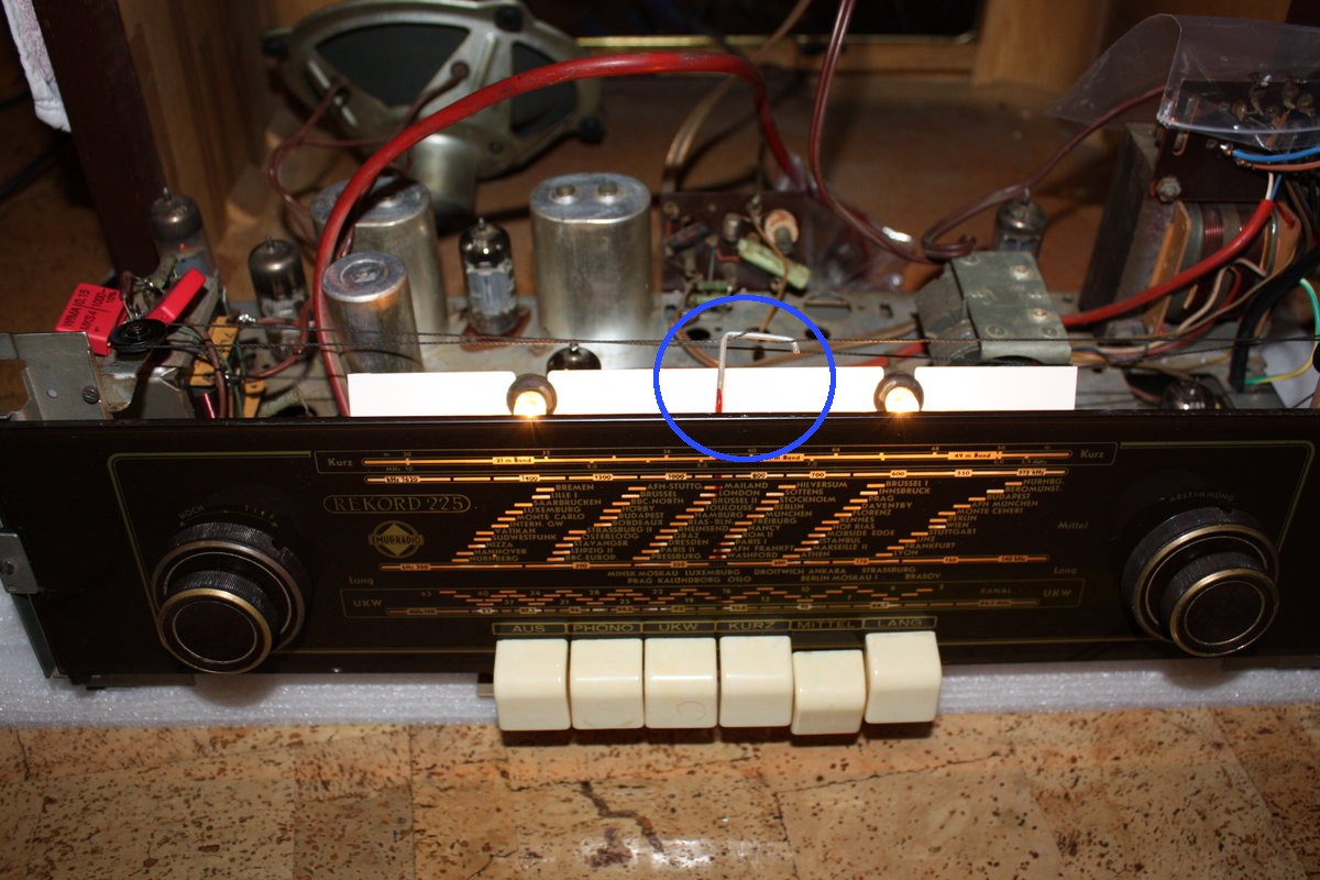
After some minor recalibrations of the tuner coils everything was working perfectly - I could thus remount the scale pointers (repainted in signal red as you can see on the blue encircled AM scale pointer), the knobs and the keyboard buttons. If you ask yourself why I put a plastic bag over the upper part of the power transformer: The two metal tips in the middle of the covered board are the power lines for the phono module - they are directly connected to AC mains...not something you want to touch accidentaly...
The tuning indicator was working, too, but as the green glow was barely visible under daylight conditions, I decided to get the tube replaced with a New-Old-Stock (= NOS) Russian one.
Currently I´m still waiting for the indicator tube being delivered. As for the rest of the radio setup everything is already working with the right voltages and temperature specifications.
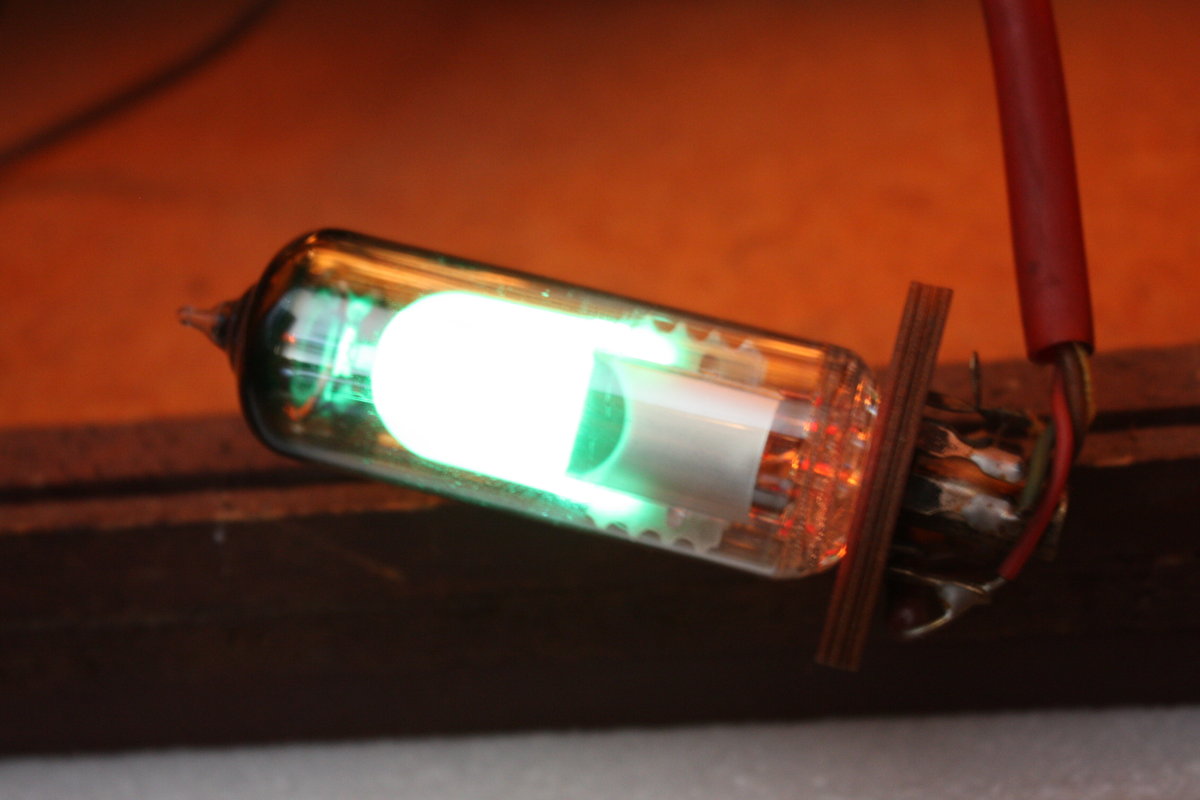
2014-04-03 New indicator tube - "first glow"
Today the Russian NOS indicator tube arrived (6E1P, virtually identical with the former EM80). The first test showed a pretty bright turquoise glow (camera settings were quite the same as for the previous "glow shot").
Installed in the radio and tuned to a strong station.
2014-05-18 Finishing the pickup and the whole project
As I was not content with the sound quality of my diy pickup I ordered a replacement part.
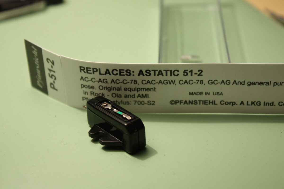
The Pfanstiehl P-51-2 - actually used to repair old Jukeboxes with Astatic 51-2 pickups - features a small crystal system with a sapphire needle.
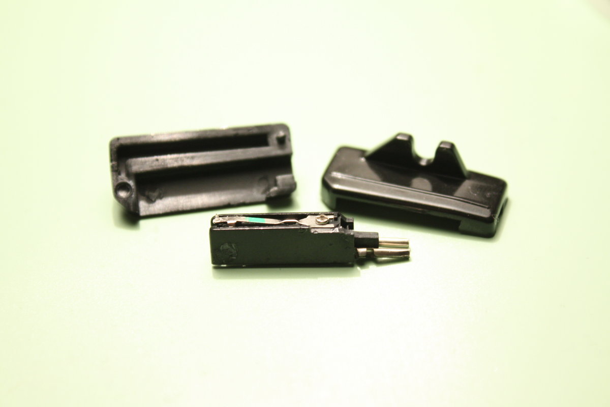
It is pretty easy to crack the case open and get the crystal system out. Due to its small size it can be fitted into almost any old pickup head.
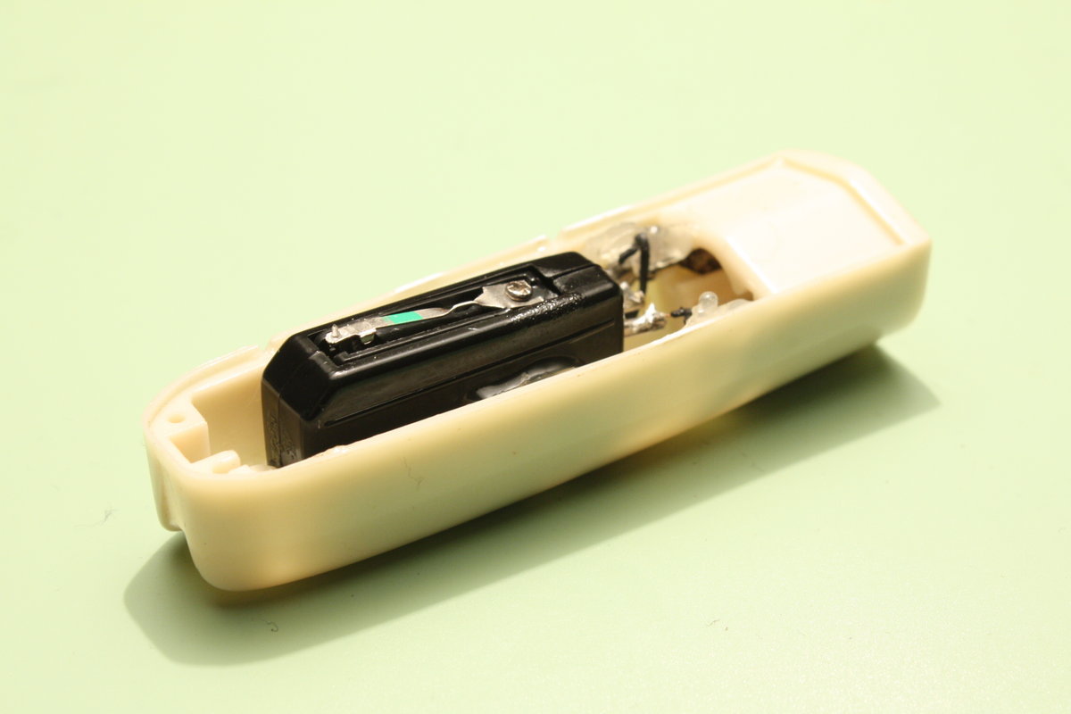
As I had already removed the original double needle system, I modified the Pfanstiehl case to fit in with the original Philips pickup head.
The concluding shots show the record player playing again...
This is how it looks inside (the white piece of paper on the left side is a printout of the circuit schematics btw)...
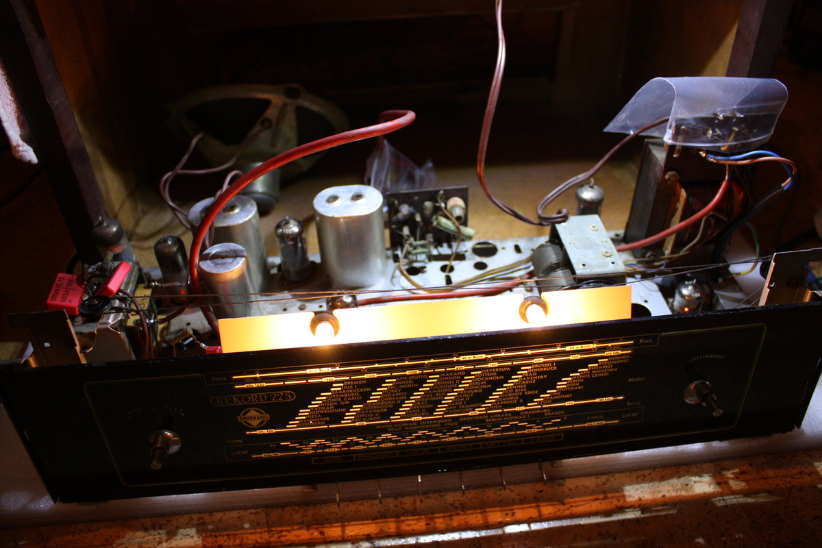
...and here tuned to a strong FM radio station (indicated by the bright green glow of the indicator tube).
Hope you enjoyed reading through the article =-)
greetings noq2
Comments